1. Types of Feed Gas
1.1 Associated Gas (from Oil Wells)
Field development is generally categorized into Gas Wells and Oil Wells. In oil fields, Associated Gas is produced alongside crude oil and requires separation through a GOSP (Gas Oil Separation Plant). The process involves:
- Desalting to remove salt to protect downstream processes.
- Exporting treated crude oil.
- Treating the associated gas to remove corrosive components like H₂S, COS, Mercaptans, CO₂, then compressing and either selling or feeding it into downstream facilities.
- Produced water from GOSP is either discharged after treatment or reinjected into the reservoir using high-pressure pumps.
- Associated gas can also be compressed and reinjected as lift gas to maintain reservoir pressure.
Typical Oil Well Processing Configuration includes:
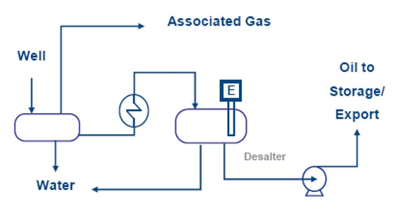
- GOSP
- Desalter
- Gas compression systems
- Reinjection systems
1.2 Non-Associated Gas (from Gas Wells)
Gas wells produce mostly natural gas and NGL (Natural Gas Liquids) such as propane, butane, and condensate. These require:
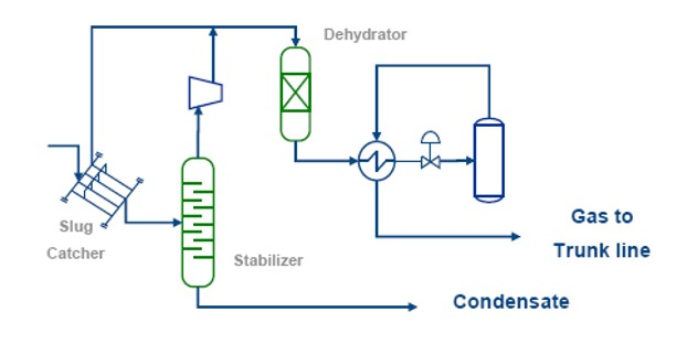
- CPF (Central Processing Facility) to remove water, impurities, and corrosive components.
- Stabilization to remove lighter components to prevent vaporization during long-distance transport.
- Routing to GSP (Gas Separation Plant) for LPG extraction and contaminant removal (e.g., mercury).
- Optional liquefaction at CPF to produce LPG, requiring effective dehydration and heavy metal removal.
A Slug Catcher or 3-phase separator is used depending on distance and slug volume.
Typical Gas Well Processing Setup includes:
- Inlet separators
- Dehydration units
- Condensate stabilization
- GSP connection
2. Products Derived from Feed Gas
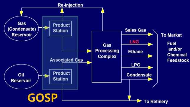
- Rich LNG (high heating value)
- Lean LNG (low heating value)
- Pipeline Natural Gas (for power or GTL plants)
- Ethane (for cracking plants)
- LPG
- NGL (mainly C5+)
- Field Condensate (Sulfur-rich, C6+)
- Plant Condensate (Sulfur-free, C6+)
- Liquid Helium
- Elemental Sulfur
3. Product(Natural Gas) Specifications
Treated Natural Gas Specs(General)
| Specification | Value |
|---|---|
| H₂O Dew Point @ 70 Bara | -12°C |
| Hydrocarbon Dew Point @ 70 Bara | -8°C |
| CO₂ (Max Vol. %) | 2.5% |
These specifications are set based on gas turbine fuel requirements and pre-liquefaction safety needs.
Typical Gas Composition:
- Methane: 86%
- Ethane: 6%
- Propane: 3%
- Butane+: 1.5%
- CO₂: 1%
- Nitrogen: 2%
- Trace: H₂S, Hg, RSH, COS
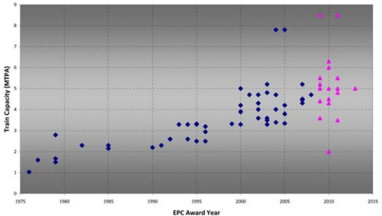
4. LNG Train Sizes / Complex Sizes
Train sizes have consistently increased since the 1970s—from ~1 MTPA to over 10 MTPA. However, bigger isn’t always better, and post-2000 data shows divergence in train sizes depending on project strategy and site conditions.
5. Key Design Factors for Gas Treatment & Liquefaction
Feed Gas Composition
- High C3+ content → affects fractionation unit size.
- Presence of Acid Gases (CO₂, H₂S) increases CAPEX significantly (+30% if H₂S > 10,000 ppm).
- Requires AGRU, sulfur solidification, and heat tracing systems.
- Strong influence on SIL level, material selection (e.g., Duplex instead of carbon steel due to SCC risks).
Feed Gas Rate
- High initial rates = fast ROI but faster reservoir decline.
- Lower initial rates = stable, long-term yield.
- Design pressure class and boosting compressors need to be balanced based on strategy.
LNG Product Specification
- Driven by turbine fuel requirements.
- Regional specifications influence fractionation strategy (Rich vs. Lean LNG).
Liquefaction Technology
- Types: Single, Pre-cooled, Cascade cycles
- Train size and regional factors influence technology license choice.
NGL Recovery
- Affects plant complexity.
- Requires stabilization, fractionation, and RVP control if blending with crude.
Meteorological Data
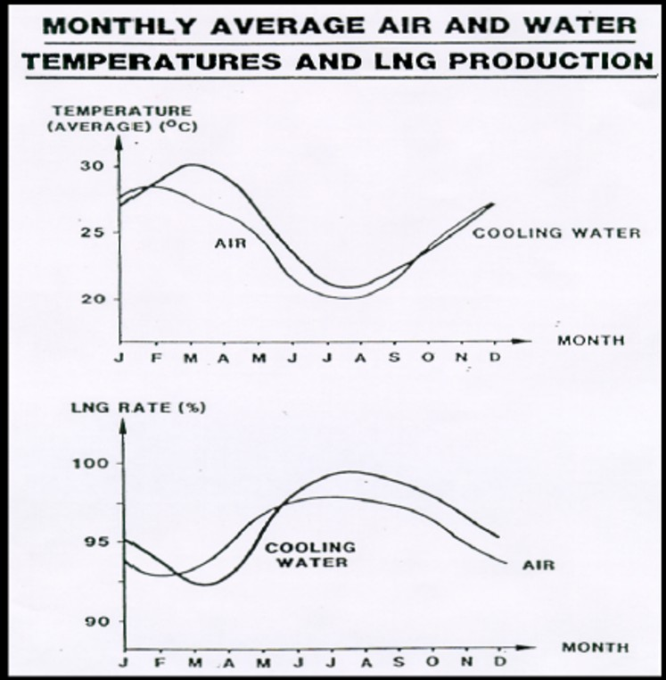
- Air/water temp impacts GT performance and condenser efficiency.
- Affects overall LNG output and energy efficiency.
Power Generation
- Remote sites require on-site generation.
- Choices: Gas turbines vs. electric motors, centralized vs. distributed power.
Compressor Design
- Types: Centrifugal (axial or tandem) vs. Reciprocating.
- Key for DPCU, liquefaction cycle, and export.
Gas Turbine Preferences
- Industrial vs. Aero-derivative
- Chosen based on efficiency, availability, maintenance, and local conditions.
6. Other Cost-Impacting Design Factors
- Targeted Plant Capacity
- Number of Trains
- Design Margins
- Reliability/Availability
- Modularization
- Site Selection
- Marine Access
- Seismic Considerations
- Plant Layout and Execution
- Project Timeline
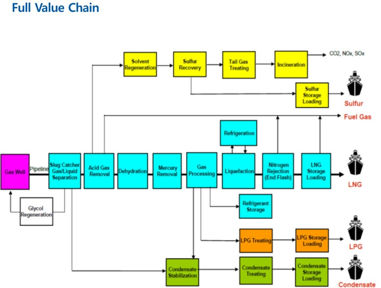
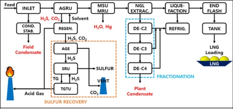
7. Full Value Chain
This part serves as an overview. Upcoming installments will deep dive into the Gas Treatment section, including Dehydration, Mercury Removal, AGRU, and NGL Recovery.
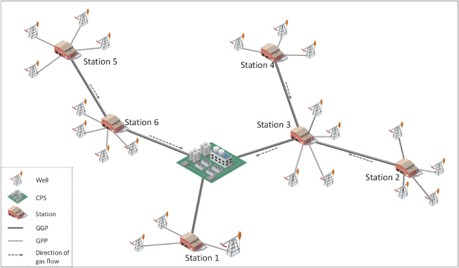
8. Gathering System
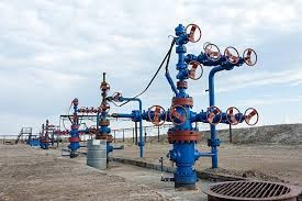
In onshore gas or oil field development, a Gathering System is essential. Although relatively unfamiliar in some regions like Korea, it plays a crucial role in field efficiency and future expandability.
Depending on the reservoir characteristics, some fields maintain a fixed number of wells, while others require continuous drilling to sustain production. As illustrated, wells are equipped with Christmas Trees, and as their number grows, a network of pipelines and equipment must connect these wells to the central processing facility (CPF)—this entire network is known as the Gathering System.
Design Coordination
Well locations are determined in coordination with reservoir engineers and the subsurface team, while the surface team designs an optimal well grouping and gathering network.
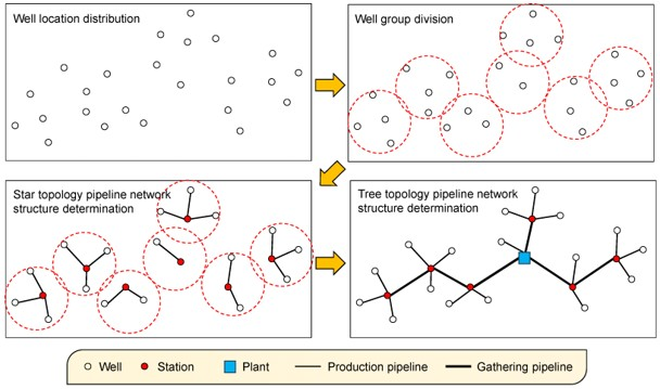
Key Components
- Gathering Pipelines
- Production Lines connect wells to hubs.
- Gathering Lines connect hubs to CPF.
- Must be designed based on total expected flow.
- Requires Flow Assurance Studies:
- Static Analysis (e.g., with Pipesim) to determine pipe diameter
- Dynamic Analysis to simulate transient flow
- Flow Regimes (for gas wells):
- Multiphase flow includes gas, oil, water, salts, and slugs
- Common flow patterns: stratified, slug, annular, etc.
- Gathering Hub
- Each well group connects to a hub
- Includes manifolds, pigging systems, vents, and drains
- HIPPS (High-Integrity Pressure Protection System)
- Protects against unexpected overpressure beyond design limits
- Alternatives: Increase pipeline schedule (costlier) or install HIPPS
- Often evaluated during FEED via HAZOP and SIL reviews
- Material Selection
- Based on PVT and corrosion analysis
- Compliant with NACE standards, includes corrosion allowances
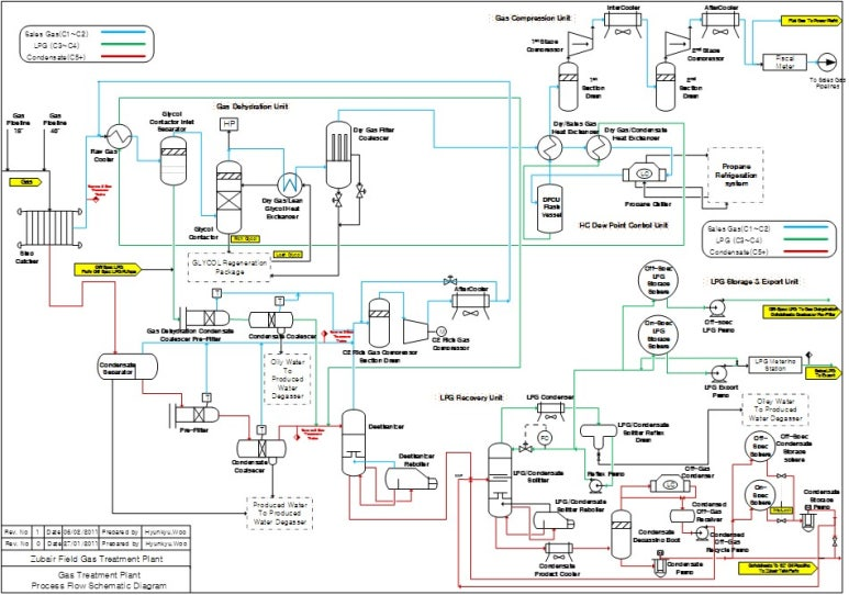
9. Gas Treatment System
The Gas Treatment System includes all facilities that process incoming raw gas (excluding the liquefaction unit). The purpose is to meet target energy content and impurity limits. It is broadly divided into:
- Inlet Facilities
- Gas Sweetening (Acid Gas Removal)
- Dehydration
- Gas Processing
- Fractionation
(1) Inlet Facilities
Incoming fluids are multiphase mixtures: gas, water, oil, salt, and mud.
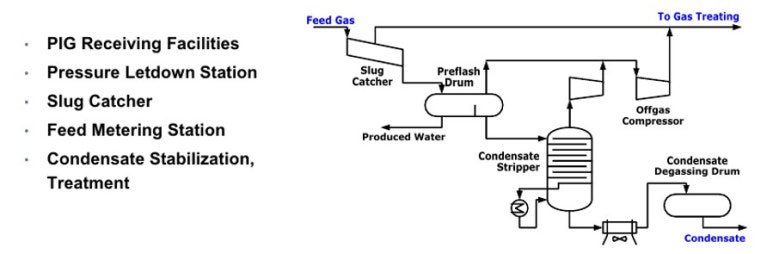
Key Equipment
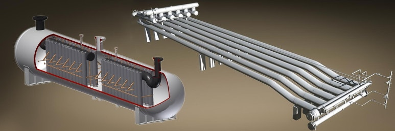
- Slug Catcher – critical to manage slug flow:
- Slug: A dense accumulation of liquid in gas flow
- Caused by: wave action, terrain, flow rate changes, or pigging
- Functions: vapor-liquid separation, surge volume absorption
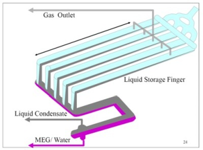
- Types:
- Finger-Type (multiple pipes): scalable, economical
- Vessel-Type: thicker walls, higher cost
- Sizing Guide:
- < 500 bbl: Vertical L-Type
- < 1500 bbl: Vessel
- 1500 bbl: Finger-Type (most economical for large slugs)
(2) Gas Sweetening (Acid Gas Removal)
What is Sweetening?
- Sweetening removes H₂S and sometimes CO₂
- Gas is classified as Sour (H₂S present) or Sweet
- H₂S poses extreme toxicity and corrosion risks
- H₂S + H₂O → acid → Stress Corrosion Cracking (SCC)
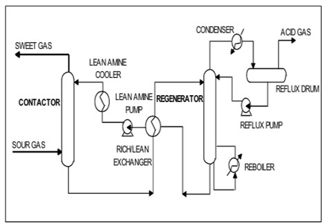
AGRU (Acid Gas Removal Unit) Components
- Amine Contactor
- Sulfur Recovery Unit (Claus Reactor)
- Tail Gas Treatment Unit
- Incinerator
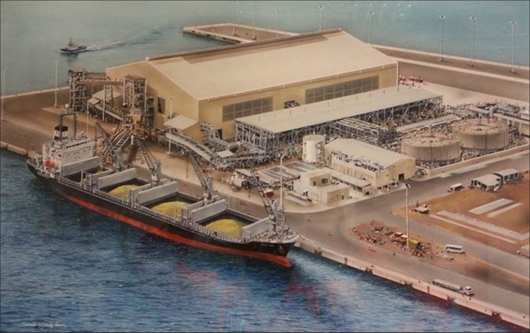
- Sulfur Storage & Loading
Amine Types
- MEA: removes H₂S & CO₂
- DEA
- MDEA: selectively removes H₂S
Contactor & Regenerator Columns
- Contactor: H₂S absorbed into amine solution
- Regenerator: heats solution to release H₂S and recycle amine
Alternative Methods
- Adsorption (e.g., molecular sieves) may be used depending on H₂S levels and cost/safety balance
(3) Dehydration
Importance
- Prevents corrosion, hydrate formation, and icing
- Ensures gas meets water dew point spec (e.g., -12°C @ 70 Bara)
Techniques
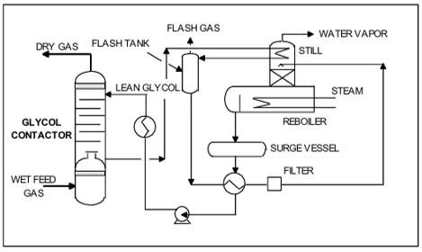
- Absorption (using Glycol)
- Most common: TEG (Triethylene Glycol)
- TEG is a liquid desiccant
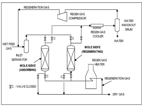
- Adsorption (using Molecular Sieves)
- Example: 4A Zeolite
- High moisture capacity, extremely low outlet moisture content (~0.1 ppmw)
- Needs at least two beds for continuous operation (one regenerating, one online)
- Example: 4A Zeolite
Comparison
- Glycol: lower cost, less effective
- Molecular Sieve: better performance, higher CAPEX
- Example: offshore uses TEG, onshore uses Molecular Sieves
- Advanced systems like Prosernat’s DRIZO approach molecular sieve performance using solvents
(4) Gas Processing (Hydrocarbon Dew Point Control)
Separates heavier hydrocarbons to meet sales gas specs:
| Spec | Value |
|---|---|
| H₂O Dew Point | -12°C |
| Hydrocarbon Dew Point | -8°C |
| CO₂ (Max vol%) | 2.5% |
Processes
- Absorption
- Joule-Thompson (J-T) Expansion
- Expander-based cooling
- Vortex separation (emerging)
J-T Process:
- Gas pressure is reduced via a J-T valve, causing cooling
- Often preceded by mechanical refrigeration (e.g., using propane)
Expander Process:
- Uses turbines to recover energy from expansion
- Improves energy efficiency over J-T valves alone
Vortex Process:
- Uses centrifugal separation to remove heavy components
(5) Fractionation (LPG Recovery)
Separates specific hydrocarbon ranges from liquids removed in upstream stages:
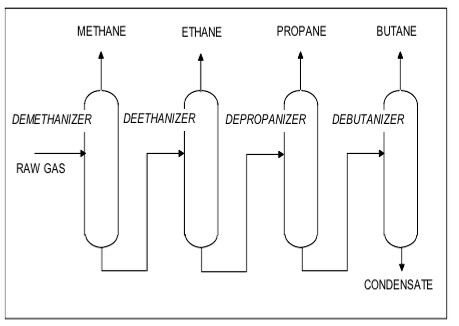
Common Columns
- Demethanizer: removes methane
- Deethanizer: removes ethane
- Depropanizer: removes propane
- Debutanizer: removes butane
Stabilizers & Splitters
- Condensate Stabilizer: removes light ends from C5+
- LPG Stabilizer: removes C1/C2 from C3/C4
- C3/C4 Splitter: separates propane and butane
- Condensate Splitter: separates light and heavy condensates
These column names reflect the component they remove or split.
10. Utility Systems (BOP – Balance of Plant)
While not covered in this installment, utility systems (power, water, nitrogen, air, flare, etc.) are crucial for main process operation.