Following the Upstream Gas Treatment, we will now talk about the liquefaction plant process.
10. Liquefaction System
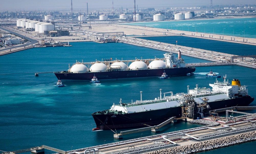
The actual view of a liquefaction plant generally resembles the photo below.
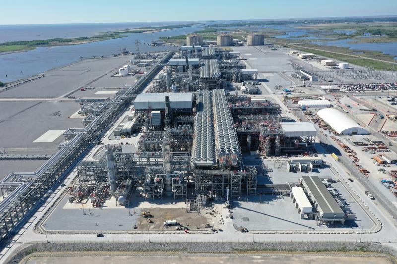
Each “Unit” is connected to form an integrated process called a “Train (TR).”
Most operating liquefaction plants consist of more than one Train, operated in parallel, and are run complementarily during regular maintenance or in emergencies. The lifespan of a liquefaction plant, if properly designed, constructed, and maintained, can be estimated to be about 40 to 50 years.
As mentioned in Part 1, the production capacity per unit Train has steadily increased from the initial one million tons to the current ten million tons.
And the core technology of the equipment that constitutes this Train is the liquefaction process.
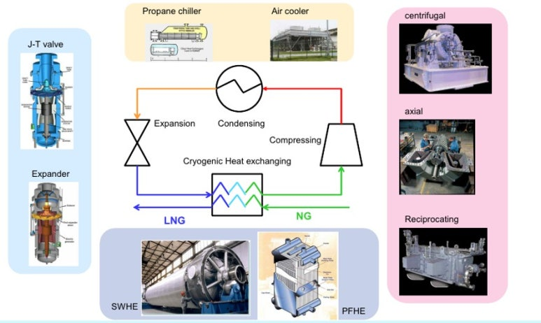
• Operating principle of the refrigeration cycle using the Joule-Thompson effect
The refrigeration cycle using the Joule-Thompson effect is a method that utilizes the drop in temperature when high-pressure refrigerant gas passes through an expansion valve or nozzle, thereby lowering pressure, to implement refrigeration. The refrigeration cycle using this effect typically goes through the processes of compression, condensation, expansion, and evaporation, and especially in the expansion phase, the Joule-Thompson effect works to achieve cooling.
- Compression:
The refrigerant gas is compressed to high pressure through a compressor. - Condensation:
The high-pressure refrigerant gas is condensed into a liquid state using cooling water in a condenser. - Expansion:
The liquid refrigerant rapidly expands and becomes low-pressure as it passes through an expansion valve or nozzle. In this process, the Joule-Thompson effect occurs, and the temperature drops sharply. - Evaporation:
The low-temperature, low-pressure refrigerant absorbs heat from the surroundings in the evaporator and vaporizes. In this process, the refrigeration effect occurs, and cooling to the desired temperature is achieved. - Cycle Repeat:
The vaporized refrigerant gas returns to the compressor and the cycle is repeated.
• Theory of Refrigeration
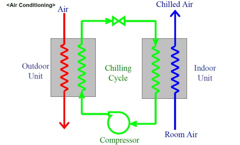
The basic model of a typical cooling cycle is the refrigerator and air conditioner (A/C) used in ordinary households. These devices use the Joule-Thompson effect to cool in the following way.
However, using only such a single cooling cycle cannot create the ultra-low temperature environment required for LNG, which is below -150℃. Therefore, a process with a dual cooling cycle as shown below becomes necessary.
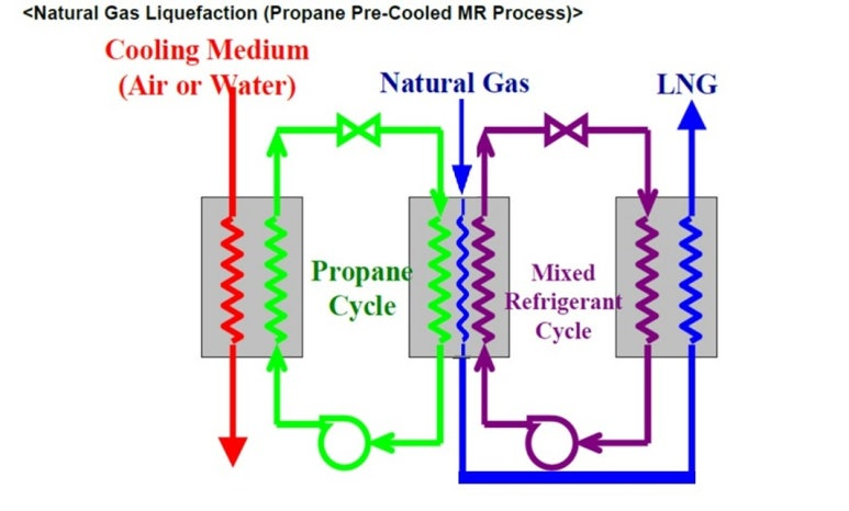
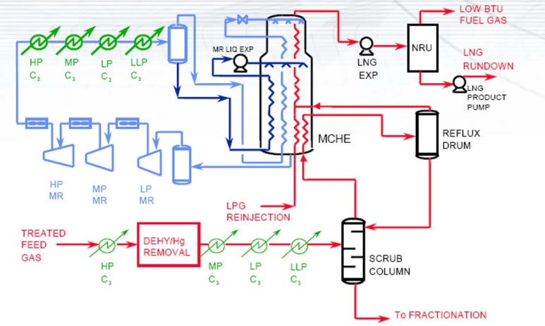
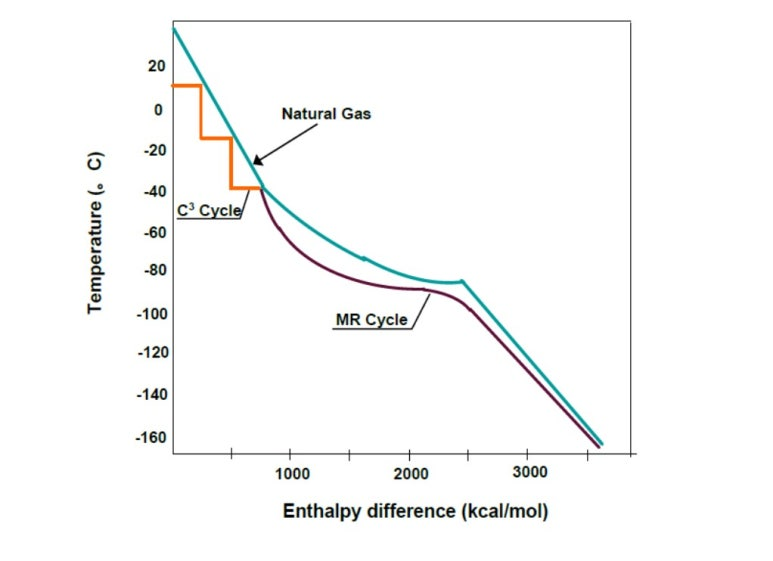
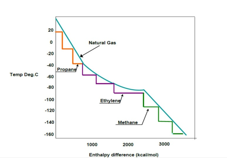
• Theory of Liquefaction
The cooling cycle shown in the figure below is a representative liquefaction cycle called the C3MR process. In the first stage, propane (C3) is used as a refrigerant to simultaneously perform the initial cooling of natural gas (about -35℃) and cooling of the mixed refrigerant. In the second stage, the mixed refrigerant is used to lower the already cooled natural gas to liquefaction temperature (-150 to -160℃).
These technologies have led to the development of various derivative (licensed) technologies in connection with the characteristics of the initial feed gas and the production volume.
• LNG Liquefaction Process Technology Options
These technologies are broadly divided as follows:
- Single Component Refrigeration
– Nitrogen expander cycles - Multi-Component (“mixed” or MR) Refrigerants
– Combination of methane, ethane, propane, butane, and nitrogen - Specific to actual feed gas to be liquefied
– MR is used to match the cold part of the cooling curve of natural gas - Pure Component Refrigerant (Cascade Cycle)
– Propane, ethylene, and methane refrigerants (at multiple pressure levels) - One, Two or Three Refrigerant Systems
– E.g. SMR, DMR, C3MR, Cascade, and AP-X (C3MR + N₂) - Two or Three Refrigerant Systems are most common today
– APCI C3MR and COP Optimized Cascade dominate the baseload LNG market
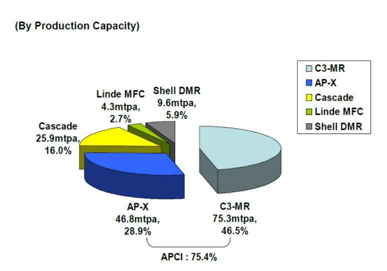
• LNG Liquefaction Process
As of 2023, in the field of liquefaction process licensors, more than 68% of the entire market is occupied by the U.S. company APCI (Air Products and Chemicals, Inc.) with its C3-MR (Propane Pre-Cooling + Mixed Refrigerant Liquefaction) and AP-X processes. ConocoPhillips’ Optimized Cascade process accounts for 23%, while others include Shell’s DMR (Dual Mixed Refrigerant), Linde’s MFC, and the SMR processes of several companies (BHGE, B&V, Charter, etc.).
In particular, recently, large-scale LNG projects composed of medium and small-sized LNG trains have been attracting attention due to their simplicity, low CAPEX, short EPC schedule, and ease of modularization. For example, in the U.S. Calcasieu Pass LNG project, BHGE’s SMR process is used, and in the Mozambique Rovuma LNG project, in which the company is participating, Charter’s SMR process has been selected.
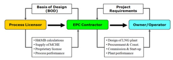
The EPC (Engineering, Procurement and Construction) market sector is monopolized by a few leading companies through strategic alliances between licensors (providers of liquefaction technology) and plant design firms.
| Licensor (Technology Provider) | EPC (Construction Company) |
| APCI : C3-MR 또는 AP-X Process | JGC(JAP), Chiyoda(JAP), KBR(UK), Technip(FRA), CB&I(US) |
| ConocoPhillips : Optimized Cascade Process | Bechtel |
• Comparison by Liquefaction Process Technology
| Description | C3-MR | DMR | Cascade | MFCP |
| Thermal Efficiency | Good | Good | Medium | Good |
| Heat Exchanger(MCHE) | SWHE (2) | SWHE (2~3) | PFHE | PFHE + SWHE(2) |
| Refrigerant Compressors (Numbers) | 2~3 | 2 | 3 or 6 | 3 |
| CAPEX | Medium | High | High | High |
| Operation Flexibility | Medium | High | Low | High |
| Operating Plants (Numbers) (CAPACITY) | 38 projects (304 MTPA) | 2 project (15 MTPA) | 18 projects (113 MTPA) | 1 project (4 MTPA) |
• LNG Process Technology Licensor
주요 액화공정 라이센서 회사를 중심으로 정리해보면 아래와 같다.
| Process | Licensor | Characteristics |
| C3-MR | APCIShell | Two refrigerant cycles [pure + mixed] Pure refrigerant: Propane (C3) Mixed refrigerant (MR): Nitrogen, Methane, Ethane, Propane Widely applied High efficiency |
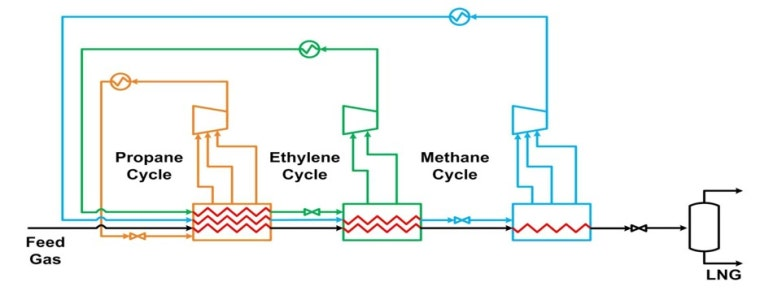
| Cascade | ConocoPhillips | Three pure refrigerant cycles (Propane, Ethylene, Methane) Well proven Standard capacity: 3.3–3.5 MTPA Bechtel is the exclusive EPC contractor ※ Recent projects involving ConocoPhillips adopted AP-X |
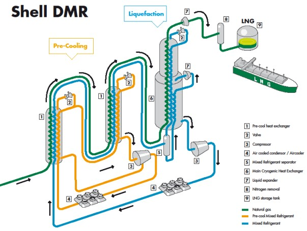
| DMR | ShellAPCI | Two mixed refrigerant cycles (Double MR) Mixed Refrigerant 1 (PMR): Ethane, Propane Mixed Refrigerant 2 (MR): Nitrogen, Methane, Ethane, Propane High efficiency and flexibility Applied to Canadian project (7.0 MTPA × 2 Trains) Shell-led projects: Prelude FLNG, Sakhalin-2, LNG Canada |
| MFC | Linde/Statoil | Three mixed refrigerant cycles (MR) Applied in Snohvit LNG Plant (4.1 MTPA × 1 Train), but had many issues |
| SMR | Balck & VeatchPRICO | Single mixed refrigerant cycle (Single MR) Widely applied in Peak Shaving LNG plants Applied in small-scale plants (up to 1.5 MTPA |
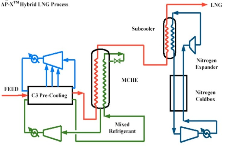
| AP-X | APCI | Three refrigerant cycles (C3, MR, N₂) Pure refrigerant 1: Propane (C3) Mixed refrigerant (MR): Methane, Ethane, Propane Pure refrigerant 2: Nitrogen (N₂) Applied in large-scale Qatar plant (7.8 MTPA × 6 Trains) ※ “X” implies a hybrid system |
And based on the number of cooling cycles applied and production capacity, the technologies are summarized as shown below.
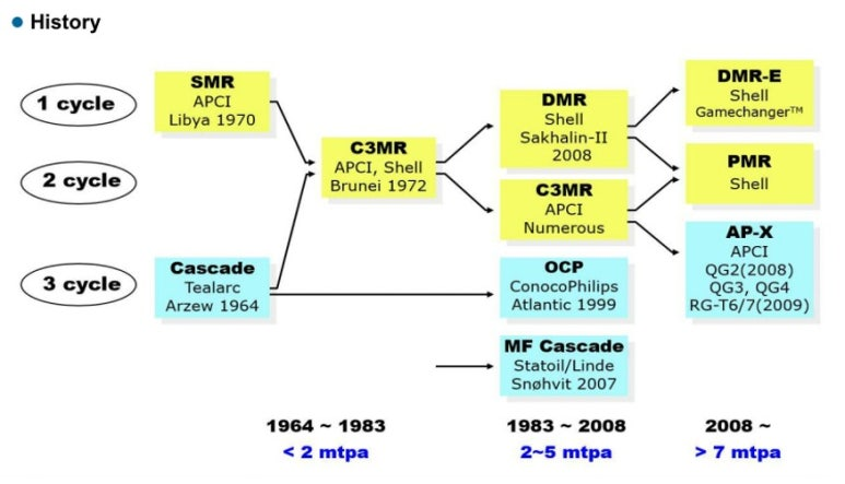
The above diagram shows why such various liquefaction technologies have been developed and why their derivatives have emerged.
Initially, the technology was developed centered around SMR, which uses a single refrigerant and has low production capacity. Then, in order to increase cooling efficiency and production capacity, C3MR was developed. Following this, DMR was developed to further improve efficiency and operational flexibility. Ultimately, DMR-E and AP-X were introduced as technologies aiming to maximize the production capacity of C3MR and DMR. As a side note, when looking at AP-X, it somewhat resembles the afterburner system of a jet fighter.
• Propane Pre-cooled MR Process
• Dual Mixed Refrigerant (DMR) Process
• Large Capacity Single Train AP-X™ Hybrid LNG Process by APCI
• Optimized LNG Cascade Cycle
LNG Liquefaction Technology
The main components that make up these cooling systems can be broadly classified into four categories:
Expander, Condenser, Heat Exchanger, and Compressor
Heat Exchanger
MCHE (Main Cryogenic Heat Exchanger) is a cryogenic heat exchanger that plays a core role in liquefaction plants. It is especially important in the process of turning gas into liquid using refrigerant in LNG (Liquefied Natural Gas) or liquefied hydrogen plants. MCHE lowers the temperature by mixing refrigerant and gas, and turns the gas into liquid. In this process, efficient heat exchange is essential to reduce energy consumption.
Main Features of MCHE:
Cryogenic Heat Exchange:
MCHE operates at extremely low temperatures and liquefies gas through heat exchange between refrigerant and gas.
Energy Efficiency:
Since the liquefaction process consumes a large amount of energy, the efficient heat exchange of MCHE greatly affects energy reduction.
Various Application Fields:
It is used not only in LNG plants but also in other sectors like liquefied hydrogen plants.
Core Technology:
MCHE is one of the core technologies of liquefaction plants, and the design and fabrication technology of MCHE determines the plant’s performance and efficiency.
Importance of MCHE:
MCHE is a critical component that directly affects the efficiency and economics of a liquefaction plant. Especially in the liquefaction of substances that must be stored and transported at cryogenic temperatures, such as LNG or hydrogen, it greatly contributes to improving energy efficiency.
Additional Information:
MCHE is the largest heat exchanger in LNG plants and is trending toward larger scale.
Recently, various research and development efforts are underway to improve the energy efficiency of MCHE.
The design and manufacturing technology of MCHE is also considered a key indicator of technological competitiveness in this field.
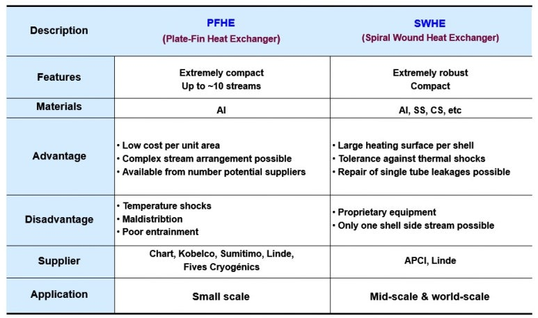
In a liquefaction plant, MCHE (Main Cryogenic Heat Exchanger) can be broadly divided into two types. The first is the spiral-wound tube type MCHE, and the second is the plate-fin type MCHE.
1. Spiral-wound MCHE:
Consists of thousands of small-diameter spiral tubes.
Mainly used by APCI (Air Products and Chemicals, Inc.).
Provides stable performance even under high pressure.
Narrow gaps between tubes result in high heat exchange efficiency.
2. Plate-fin MCHE:
Constructed by stacking plates and fins made of aluminum alloy.
Provides high efficiency under high pressure and allows miniaturization and weight reduction.
Recently trending toward large scale, and applicable to various sizes of plants.
Traditionally has been widely used in LNG plants.
Condenser
A condenser, in general terms, is referred to as a cooler. In other words, it is a piece of equipment that cools high-temperature refrigerant gas compressed through a gas compressor. Therefore, it is sometimes labeled as a Cooling System. Depending on its purpose and thermodynamic function, it can be either a condenser or a cooler.
The key point of such a condenser is which medium—air or water (including sea water)—is used for cooling.
In other words, it is a matter of Air Cooling vs. Water Cooling.
The recent trend is that newly built LNG plants prefer air cooling due to environmental issues when using seawater. Water cooling is now generally limited to expansion projects of existing facilities.
When comparing these two cooling methods, the following can be noted:
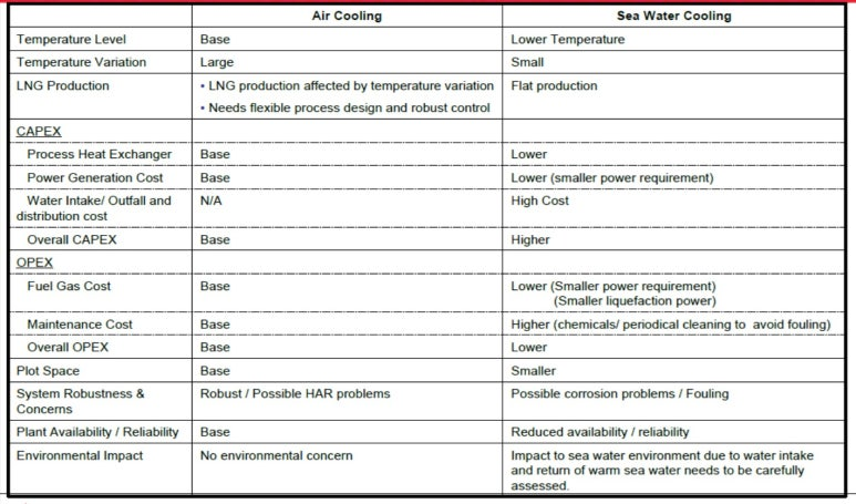
The issue lies in environmental variables.
As mentioned in Previous Section(Upstream Part), when using a mechanical refrigeration system based on the Joule-Thomson effect, environmental conditions—namely, climate—have a significant impact. Especially in high-temperature environments, the efficiency of air cooling drops noticeably, so this must be considered in the design phase.
Of course, as noted in the previous comparison table, each method has its own pros and cons in terms of initial capital investment and future operating costs. Therefore, it is essential during the early conceptual design or FEED stage to perform thorough comparison and analysis to determine the best option.
If the facility is located far from rivers or the sea or cannot reliably secure industrial water, it may be possible to achieve the target temperature by increasing the operating pressure of the refrigerant cycle, boosting gas compressor capacity, and expanding the Air Cooler (Condenser). However, this inevitably results in increased capital and operating costs.
Therefore, if possible, it is wise to consider Water Cooling (including sea water) as a viable option.
Compressor Driver
A gas compressor is required to compress the refrigerant. At this point, the first thing to consider is the selection of the compressor’s driver type.
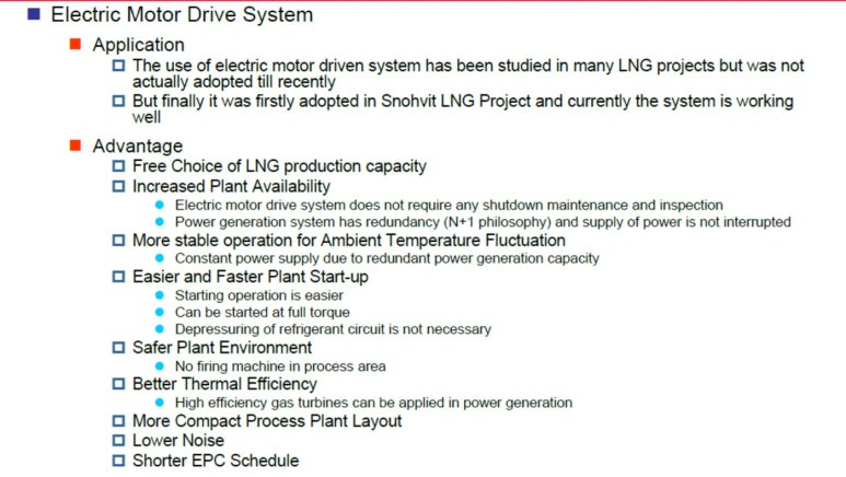
In liquefaction plants, the compressor drive for refrigerants is generally either Electric Motor Driven or Gas Turbine Driven. The electric motor drive uses an electric motor to drive the compressor, while the turbine drive uses steam or gas turbines. Each method has its pros and cons, and the appropriate method is selected depending on the plant’s characteristics and operational requirements.
1. Electric Motor Driven:
Advantages:
- Easy to maintain and relatively low operating costs.
- Takes up relatively less space and allows for easier operation control.
- Can be applied to various compressor capacities and allows flexible operation.
Disadvantages:
- Dependent on power supply; operation may stop during blackouts.
- In the case of high-capacity compressors, power consumption can be substantial.
2. Gas Turbine Driven Method:
Advantages:
- Suitable for driving high-capacity compressors and offers high efficiency.
- Can use steam or gas as an energy source, thereby increasing fuel efficiency.
- Capable of operating independently even during power outages, enabling stable operation.
Disadvantages:
- Maintenance is complex and operating costs are relatively high.
- Requires a large installation space and may generate noise and vibration.
- Component wear may occur due to high-speed rotation.
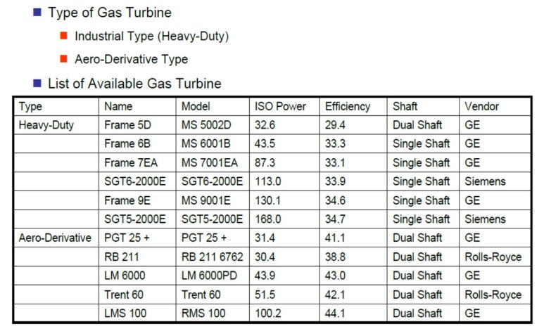
There is also something to consider when selecting a gas turbine as the driver. That is the choice between the Industrial Heavy Duty Type and the Aero Derivative Type.
Industrial Heavy Duty gas turbines and Aero Derivative gas turbines differ in design purpose and characteristics. Heavy Duty turbines are suitable for applications requiring long-term stable operation and high reliability, such as power generation and petrochemical processes. Aero Derivative turbines are based on aircraft engines and are characterized by their lightweight design, high power density, fast start and stop, and flexible operating conditions.
Industrial Heavy Duty Gas Turbine:
Advantages: Stable long-term operation, high reliability, long lifespan, high efficiency
Disadvantages: Relatively heavy and bulky, high initial investment cost
Applications: Power plants, petrochemical plants, LNG plants
Aero Derivative Gas Turbine:
Advantages: Lightweight, compact, high power density, fast start/stop, flexible operation, easy maintenance
Disadvantages: Relatively shorter lifespan, possibly lower fuel efficiency
Applications: Power generation, gas pipeline compression, emergency power supply for oil and gas industries, backup power facilities
Key Comparison Items:
| Item | Industrial Heavy Duty (Gas Turbine) | Aero Derivative (Gas Turbine) |
| Weight & Size | Heavy & Big | Light & Small |
| Output Density | Low | High |
| Time for Start & Stop | Slow | Fast |
| Life Span | Long | Short |
| Efficiency | High | Middle – Lower |
| Maintenance | In Situ | Vendor Shop |
| CAPEX | High | Low |
| Operational Condition | Stable Circumstances | Flexible Circumstances |
| Applied Markert | Power Plant, Chemical, LNG | Power Plant, Gas Pipelines, Emergency Power |
3. Other Drive Methods(Internal combustion engine drive)
Used in small-scale liquefaction plants or emergency power facilities.
4. Selection Criteria:
(1) Plant Scale:
Gas turbine drives are mainly used in large-scale plants, while electric motor drives are common in small-scale plants.
(2) Operating Conditions:
For cases where stable operation is critical, gas turbine drives are suitable.
If efficiency is more important, electric motor drives are recommended.
(3) Cost:
The decision is made based on a comprehensive evaluation of initial capital cost and operational expenses.
Expander
As mentioned earlier, the basic principle of cooling is adiabatic expansion using the Joule-Thomson (J-T) effect, which is the principle behind the J-T valve.
J-T Valve in Liquefaction Plants:
The J-T valve is a fluid control valve used to liquefy gas based on the Joule-Thomson effect.
As high-pressure gas passes through the valve and rapidly loses pressure, its temperature drops significantly. This principle is crucial in cooling gas to its liquefaction temperature, especially in LNG or liquid hydrogen plants.
Operating Principle:
- High-pressure gas supply:
Gas is compressed to a high-temperature, high-pressure state via a compressor. - Expansion through the J-T valve:
The high-pressure gas passes through the valve, undergoing rapid pressure drop. - Temperature drop and liquefaction:
Due to the Joule-Thomson effect, the temperature of the gas drops sharply, leading to liquefaction.
Key Roles and Features:
- Cooling & Liquefaction:
A critical component for liquefying gas by cooling it to the required temperature. - Energy Efficiency:
Enables fluid cooling through the J-T effect; when used with a turbo expander, it enhances process efficiency. - Broad Application:
Used not only in LNG but also in liquid hydrogen and other gas liquefaction processes. - Control Function:
Acts as an automatic control valve operated purely by fluid pressure, regulating flow and temperature.
However, with technological advancements and a focus on energy efficiency, the Expander (Turbo Expander) has emerged as a key component that expands gas to lower temperatures more effectively than a J-T valve. It improves cooling efficiency and harnesses expansion energy to generate electricity or drive compressors. It is widely used in ultra-low temperature processes like air, LNG, and hydrogen liquefaction.
Role and Principle of the Expander:
- Cryogenic Cooling:
As gas expands through the expander, it performs external work, resulting in energy loss and a significant drop in temperature. - Efficiency Improvement:
Reaches lower temperatures than the J-T valve method, enhancing cooling and liquefaction efficiency. - Energy Recovery and Use:
The energy from expanding gas can be used to generate electricity or power compressors, reducing process energy costs.
Main Application Areas:
- Air Liquefaction:
Used in air separation units to liquefy air at ultra-low temperatures. - LNG Liquefaction:
Expands incoming natural gas at the plant inlet to produce a liquid stream of cooled natural gas. - Hydrogen Liquefaction:
A key device in hydrogen liquefaction strategies, used to liquefy hydrogen under cryogenic conditions.
This concludes for a brief review on gas production and liquefaction processes.